
My parents’ old LCD TV started failing, and given its age, we decided that it made more sense to replace it with a modern set featuring all the latest features rather than attempt repairs on an outdated unit full of limitations.
Instead of discarding the old television, I saw an opportunity: why not repurpose it as an artificial daylight lamp? The idea had been lingering in my mind ever since I converted old laptop screens into car monitors years ago. When this Samsung LE37M86BD became available, the timing felt right to finally try it.
This 37-inch model is an LCD TV with CCFL (cold cathode fluorescent lamp) backlighting. A LED-backlit panel would have been ideal for this project, but I’m determined to see how much I can salvage from the existing setup. The goal is simple: try to keep a fully functional power supply and backlight system while completely bypassing/omitting all the television-specific circuitry and functions.
Tear down!
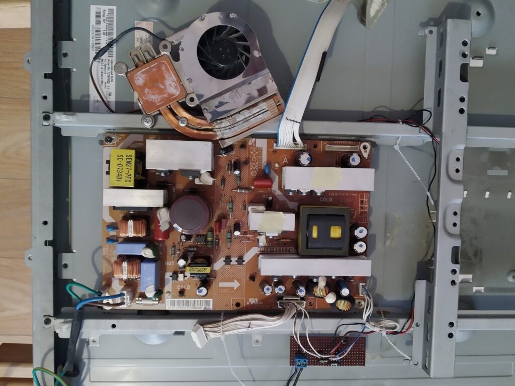
First I had to find out if it would be possible to convert this television into a permanent light. So I started to disassemble it. When opening the backside the main components immediately became visible.
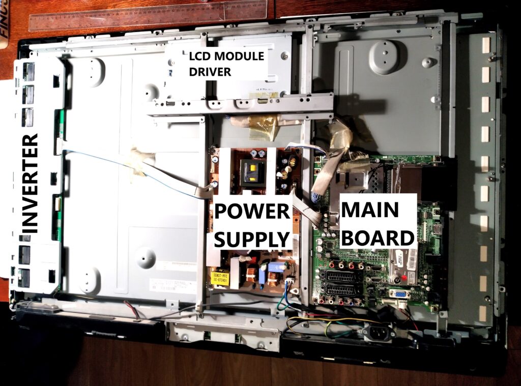
I started by removing the speakers at the bottom, then carefully disassembled all the boards. My goal was to inspect everything closely for any signs of damage and to note down the model numbers of each board for reference.
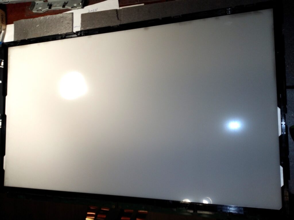
Then I flipped the panel over to get a good look at the display from the inside. I already had a pretty clear idea of what I’d find, but I wanted to see it with my own eyes—especially to check whether all the CCFL tubes were still intact and in decent condition.
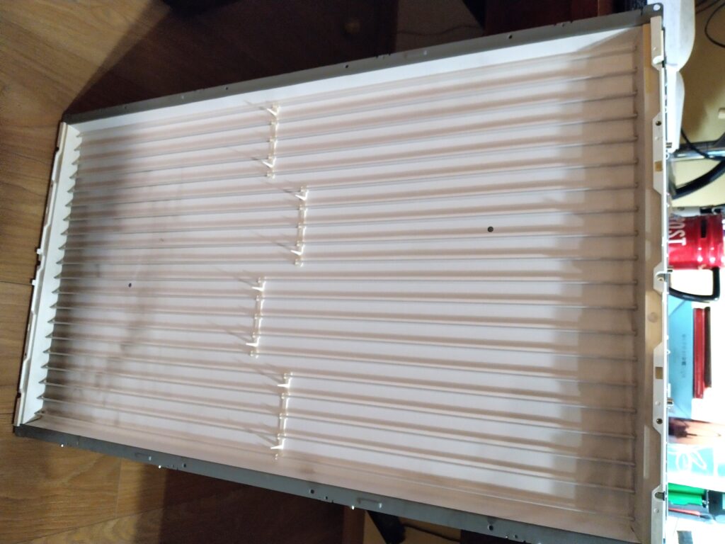
I removed the lcd panel and the frame from the backlight. As expected a variety of diffusers were in front of the set of fluorescent tubes. Everything looked normal so I simply put everything back together to protect the fluorescent tubes. I omitted the lcd panel as this one would no longer be needed.
Power supply
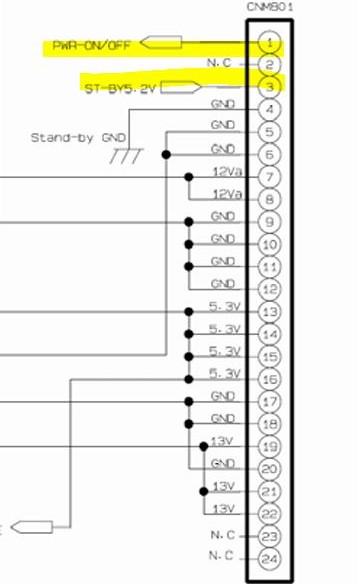
I considered myself very lucky when I found a test certificate of this television series which contained the complete schematics of the power supply:
After studying the schematics, the standby and power-on behaviour became clear.
- When power is applied to the power supply, the standby circuit should power on.
- The main board is connected to the power supply via connector CNM801.
- To simulate a power on-on command, I bridged the 5.2 V standby voltage (from pin 3) to pin 1 (PWR_ON/OFF)
- As expected the power supply turned on fully. I was able to measure 24 V on the output connector feeding the inverter.
With the power supply’s standby and main circuits functioning it was time to go to the next component.
Inverter
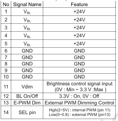
Now it was time to see how I could get some light out of the backlight when connecting it to the power supply. Once again luck was on my side when I found the datasheet for exactly this display: AU Optronics T370HW02 V2:
The datasheet contains a pinout of the connector of the inverter which has enough information to be able to power it on.
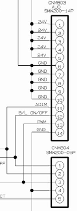
As luck would have it, pins 11, 12, and 13 of the inverter connector are conveniently routed out again through connector CNM804 on the power supply board. This made testing straightforward: I simply applied 5.3 V to pin 12 (BL_ON/OFF), and the backlight fired up instantly.
The datasheet specifies 3.3 V for the backlight enable signal, but since the power supply doesn’t provide a direct 3.3 V rail and the logic threshold is typically forgiving, I figured 5.3 V would be safe enough—and it worked without issue.
With plans to eventually mount this as a ceiling light, I wanted to stress-test the setup first. I put the panel on sawhorses, powered it on, and let it run continuously for several hours.
The backlight performed flawlessly throughout the test. However, I noticed that some heatsinks on the power supply board and the high-voltage transformers on the inverter were getting quite hot to the touch. Clearly, heat management will need some attention moving forward.
Cooling
The display and electronics were conceived to be positioned vertical. This was clearly visible in the orientation of the heat sinks, which are optimized for natural airflow. I am going to put the display horizontal and to make matters worse, it will be running on maximum brightness continuously.
In the earlier stress test, the hottest heatsinks and high-voltage transformers reached around 65 °C. While this temperature is generally well within safe limits for the components, the horizontal mounting combined with permanent maximum-power operation represents a significant departure from the TV’s intended usage. To ensure long-term reliability, I decided to try to reduce those temperatures.
Fortunately, the power supply provides a handy 5.3 V rail. I connected a small 5 V laptop cooling fan and directed its airflow across the hottest heatsinks. This simple addition dropped their temperature to a very comfortable ~40 °C—more than adequate for my needs.
The high-voltage transformers on the inverter board, however, are spread quite far apart, making effective cooling with a single fan challenging. Rather than complicating the build further, I’m now considering a different approach: slightly reducing the overall backlight brightness. This would lower power draw and heat generation across the entire system while still delivering plenty of usable daylight-like illumination.
Dimming the backlight
To keep the setup as minimal as possible, I wanted to find a simple way to reduce the backlight brightness while completely eliminating the main board and LCD module board.
Reviewing the panel datasheet (for the AUO T370HW02), I noticed that pin 11 on the inverter connector is labeled Vdim— described as “Brightness control signal input: (0 V min ~3.3 V max).”
Further research confirmed that CCFL inverters of this era typically support two brightness control modes:
- External PWM mode — where the LCD module provides a PWM signal.
- Internal PWM mode — where an onboard controller generates the PWM, and brightness is adjusted via an analog voltage on the dimming pin.
The operating mode is selected by the voltage applied to pin 14 (SEL pin). When pin 14 is pulled high (2–5 V), the inverter switches to internal PWM control. In this mode, the overall brightness is then regulated by applying an analog voltage between 0 V and 3.3 V to pin 11 (Vdim).
This configuration looked ideal for my project: by keeping pin 14 high, I could achieve simple analog dimming without needing the original main board or any external PWM circuitry.
To enable internal analog dimming mode, I needed to pull pin 14 high. On the power supply board, this pin was tied to the ground to have it low, so I carefully cut that single wire from the wire bundle between the inverter and power supply, then extended it and connected it to the available 5.3 V rail.
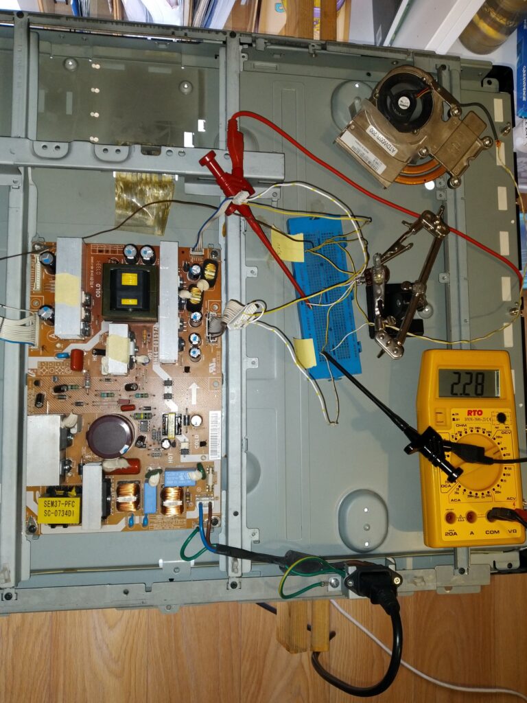
Next, on a breadboard, I wired a 10 kΩ linear potentiometer across the 5.3 V rail and ground, and connected the wiper (middle pin) to pin 2 of connector CNM804 — which is internally linked to pin 11 (Vdim) on the power supply. To keep an eye on things, I also connected a multimeter to monitor the voltage on the dimming line.
The setup worked perfectly right away. As I turned the potentiometer and dropped the voltage below ~3.3 V, the backlight brightness decreased noticeably and smoothly. After some experimenting, I settled on a setting (2.3V) that gave a subtle but perceptible reduction — roughly 10% dimmer by eye (hard to quantify precisely without a light meter though).
I left the panel running for about an hour at this reduced level and re-checked the temperatures. The heatsinks and high-voltage transformers were about 5 °C cooler than at full brightness. While not a dramatic drop, it’s an improvement for long-term operation. The lower power draw and reduced stress on the tubes, transformers, MOSFETs, and capacitors should contribute positively to the overall longevity of the setup.
Final setup
To convert the temporary test setup into a permanent, reliable solution, I first measured the resistances on either side of the potentiometer in its final dimming position: 5.1 kΩ and 4.95 kΩ.
The closest fixed resistors I had on hand were 2.18 kΩ and 1.98 kΩ. I inserted them in series on the breadboard to simulate the divider — this gave me ~2.8 V on the Vdim line (a bit higher than my test setting, but the brightness reduction was still clearly noticeable and acceptable, so I decided to proceed with it).
I then transferred the two resistors to a small piece of perfboard. On this board, I soldered connections to ground and the 5.3 V rail (both taken from connector CNM801 on the power supply). From connector CNM804, I soldered BL_ON/OFF directly to 5.3 V (to keep the backlight permanently enabled) and Vdim to the junction between the two resistors.
I also pulled pin 14 of the inverter connector high by connecting it to 5.3 V (enabling internal analog dimming mode).
Finally, I wired the 5 V laptop cooling fan directly across ground and 5.3 V for constant operation.
One issue remained: unplugging the power cord abruptly caused noticeable flickering as the backlight shut down unevenly. To achieve a clean, “soft” power-off, I brought the PWR_ON/OFF signal and the 5.2 V standby voltage out to an external toggle switch. This allows proper sequenced shutdown without stressing the inverter or tubes.
I screwed the perf board to the panel using some of the mounting holes of the main board.
To mount the ventilator I reused the original heatsink form the laptop fan assembly to which the ventilator was securely attached. I attached the heatsink with two screws to the panel.
Lastly, I neatly routed and secured all the added wires with zip ties to keep everything tidy and vibration-resistant.
I also reoriented the C14 power inlet connector so the power cord now exits from the side of the panel instead of the rear/top. This change allows the panel to be mounted much closer to the ceiling or wall.
Evaluation
Time to take a step back from the fun of researching and tinkering with this little project and look at it more objectively.
The datasheet lists the panel’s luminance at 550 cd/m². With an active area of 46 × 82 cm (≈ 0.377 m²), a quick calculation gives a total luminous flux of roughly 650 lumens at full brightness (Φ = luminance × area × π).
I measured the power draw at my current reduced-brightness setting and got about 160 W. That works out to an overall system efficiency of ~4 lm/W.
For comparison, a typical LED strip produces around 1000 lm/m at 10 W/m → 100 lm/W.
So, even after accounting for PSU losses for a led strip, the CCFL panel is roughly 20 times less efficient than a modern LED strip setup.
After reading a bit about CCFL technology: the lamps themselves usually manage only 30–60 lm/W, and then you add significant losses in the inverter, power supply, diffuser stack and light-guide/edge effects. At reduced brightness the efficiency drops even further, so 4 lm/W is actually plausible.
In short: this repurposed TV panel is basically a 160 W space heater that happens to emit some light on the side.
If the goal is simply a large, even panel light, the far smarter (and lighter) choice would be to mount some LED strips on a metal sheet or diffuser board — no need to lug around a 12 kg heater. 🤣🤣🤣
Conclusion
The project ultimately turned out exactly as I had envisioned: stripping away all the unnecessary TV circuitry and getting just the backlight running off the power supply alone.
The light it produces is a fairly cool white, but surprisingly it doesn’t bother me at all. I normally find most cool-white LED bulbs far too harsh and clinical, yet this panel feels comfortable and easy on the eyes. I suspect the difference lies in the fact that the light comes from a very large, diffuse surface rather than a concentrated point source.
The cold-shower moment came when I realized I had essentially built a 12 kg space heater that happens to emit some light on the side…
I’m not ready to scrap it just yet. I’ll remove the brightness reduction and let it run at full power. Given its dismal efficiency, there’s little point in babying it to extend its life. If (when) it fails, I’ll simply recycle it. With the fan cooling the power supply, I expect the inverter or CCFL tubes will be the first to go—after which I can salvage the 24 V power supply for future projects.
For now, I’ve reinstalled the panel back into its original TV housing. At 12 kg and those dimensions, it’s undeniably cumbersome to handle and mount.
Overall, I’m satisfied: I managed to pull off exactly what I set out to do, and the modification went according to plan. That said, I can’t help feeling a little disappointed by the final efficiency of the result.
I could, of course, replace the CCFL tubes and inverter with LED strips and a smaller power supply. That would make it far more efficient but it would remain heavy and bulky. Honestly, simply mounting some LED strips on a thin metal sheet would deliver much higher brightness with a far more minimalist and practical result.
For the time being, I plan to hang the panel from the concrete ceiling in my workshop and try it out. Maybe it’ll find its purpose. If not, it’ll head to recycling without regret.