
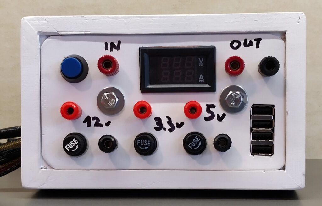
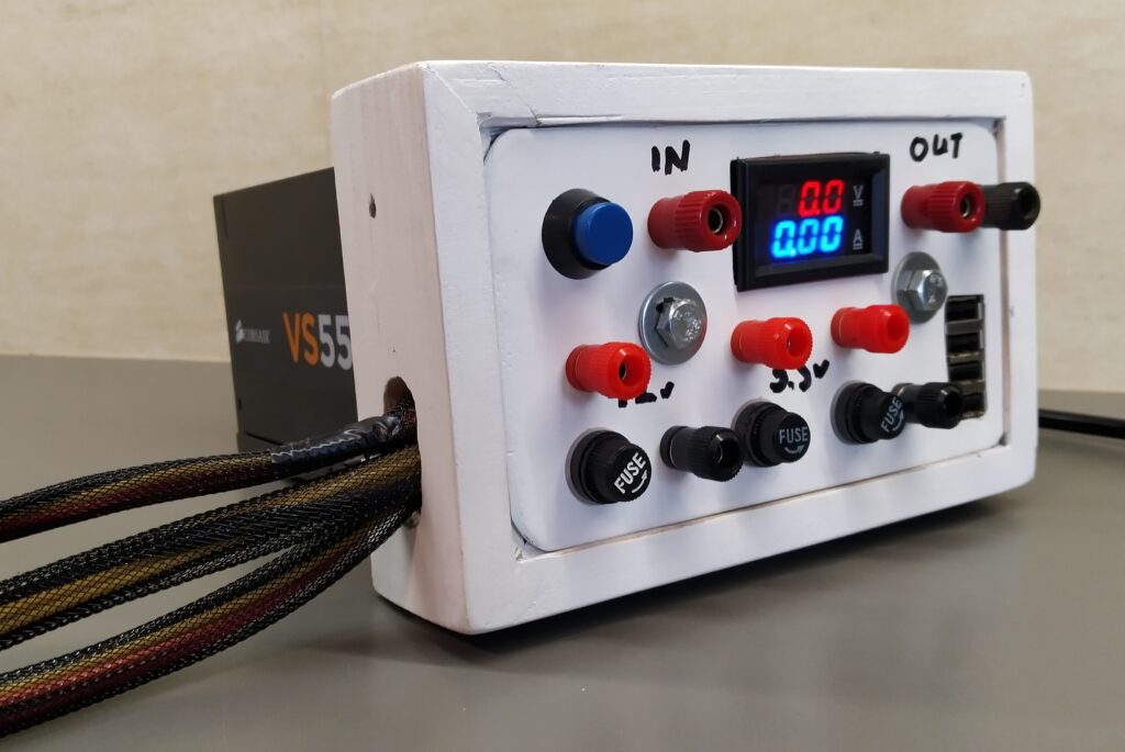
12V, 5V and 3.3V with enough power behind it not to worry anymore about overloading. 4 USB charging ports. A voltage/current meter and possibility to connect peripherals later.
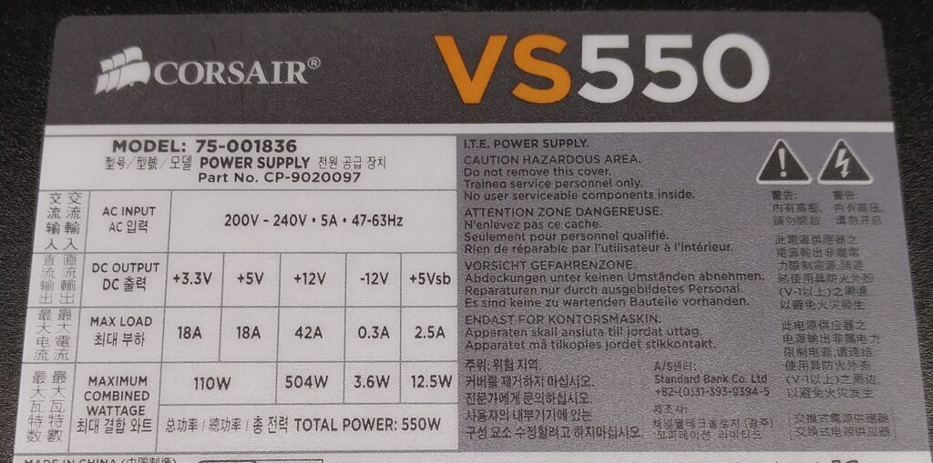
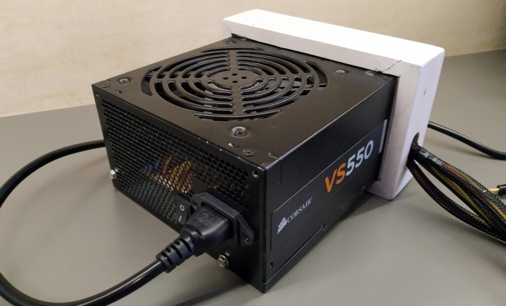
For another upcoming project I needed a sufficiently large 12V power supply. I needed at least 200W of peak power. I decided to repurpose a power supply from an old PC. I had a Corsair VS550 available. It has a maximum power of 550W and for the 12V rail it can deliver 504W. More than enough for what I needed. According to AI the usability of this power supply for future PC builds would be limited and I didn’t really see myself building a new PC in the nearby future so I didn’t feel guilty repurposing this perfectly fine PSU.
Research
A bunch of wires come out of the PSU. They are packed together in nylon sleeves with various connectors at the end to power the different peripherals in a PC. After opening up the PSU and pulling back some of the nylon sleeves I could distinguish the following colours:
- Black: ground
- multiple wires to various connectors
- Yellow: +12V
- multiple wires to various connectors
- Red: +5V
- multiple wires to various connectors
- Orange: +3.3V
- multiple wires to various connectors
- Blue: -12V
- Typically very low current rating. 0.3A for my PSU.
- Green: power on
- When this one gets connected to the ground, the power supply will go from standby to ON.
- Grey: power ok
- Will supply 5V status voltage when the power supply is working properly.
- Purple: 5V standby voltage (Vsb)
- Is always on when the power supply is switched on/connected to the mains (2.5A current rating for my PSU)
- Thin orange: 3.3V sense line
- This wire detects if the 24 pin socket to power the motherboard is fully seated. If it detects 3.3V it will fully power on the power supply. (In my PSU it is crimped together with a normal 3.3V wire in pin 13 of the socket so it basically serves no purpose…) On some PSU’s this wire can be brown.
Mains power on switch
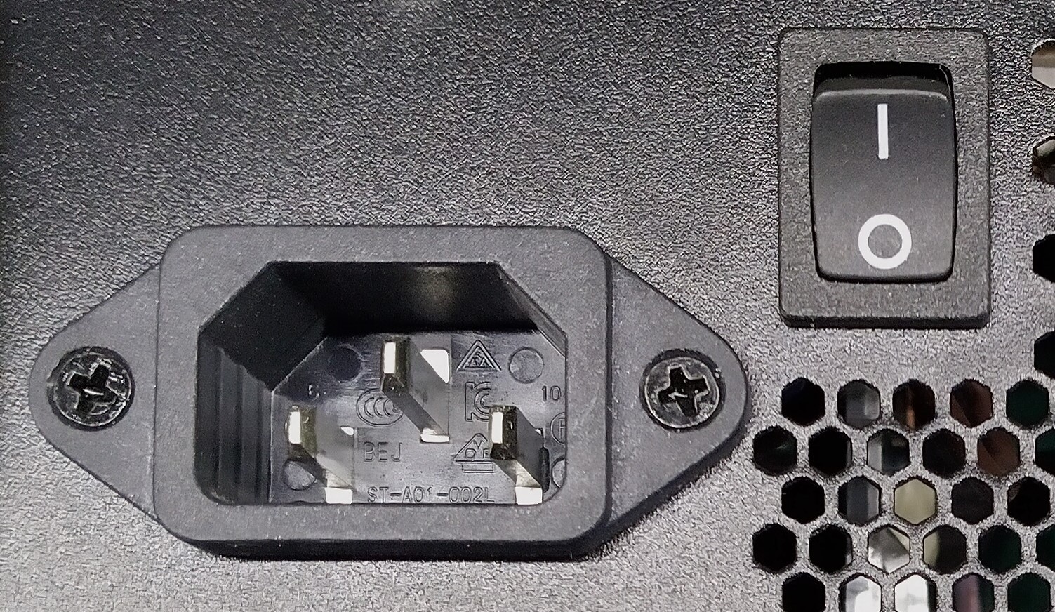
Most PSU’s have a mains power switch at the back. For safety reasons I decided not to bring this switch forward to the control panel as not to mix the 230V and the lower output voltages of the PSU.
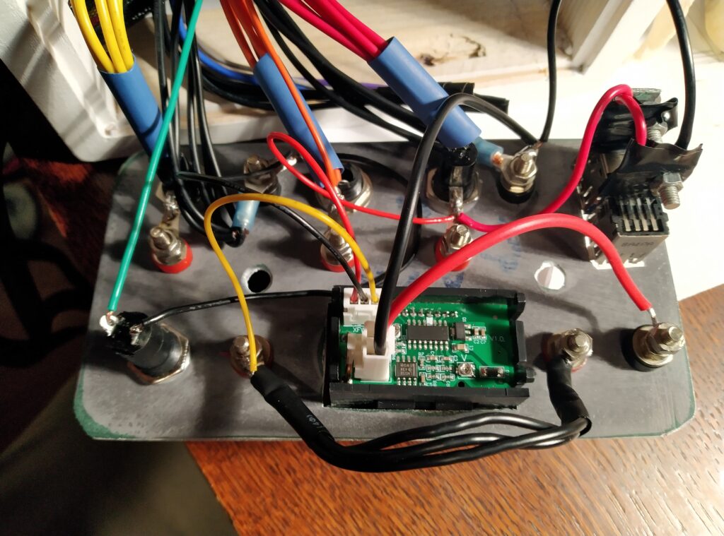
Adding a voltage & current meter
A variety of cheap voltage/current meters can be found online. I tested one for a previous project and was satisfied with it’s accuracy. The datasheet claims that it can measure up to 100 V DC and 10 A DC. Seeing the thin connections wires though I have my doubts that it will be able to withstand 10 A continuous… A point of attention is that the meter measures the current in the ground wire so the ground output from the meter is not the same as it’s input. The meter needs 4.5V to 30V supply voltage for it to function so I connected it to the 5V rail. The thin red and black wires are needed for the supply voltage, the thin yellow wire is the voltage measurement, the thick black and red wires are for the voltage measurement. (Please check the electrical drawing for further clarity.) I made a small jumper cable so I could connect the meter to whatever output voltage I would want.
Possibility to connect peripherals
Besides having 12 V & 5 V available in my workshop to do some testing, I want to use the power supply to permanently power other equipment which needs 12V. I decided not to cut the 3 longest wire bundles and somehow guide them outside of my power supply. When needed I will be able to put a connector of my desire on them and power whatever I would want with 3.3, 5 or 12V.
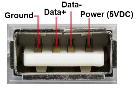
I also recovered 2 double USB ports from old laptops and will add them as charging ports on the front of the power supply.
Electrical connections
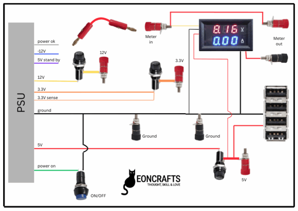
The below drawing shows all electrical connections that I made from the PSU to the various components. In various other blogs on converting a PSU a power resistor is inserted to put a load on the 5V rail to make the PSU work properly. The PSU which I am converting is working just fine without such resistor.
I did not use the power_ok, 5V standby and -12V wires from the PSU. I cut them off at about 15 cm and put some shrink tube over the end.
For the ground I only included 2 black sockets as I didn’t have anymore place in the housing that I was planning on using. For a PC, the housing is connected to the ground of the PSU so no need to pay particular attention on keeping the ground isolated. This came particularly in handy for the connection of the USB ports.
According to the manual, the PSU I have has both an over-power and a short circuit protection so no additional safety devices are needed. For good measure though, I added a 10A fast glass fuse on each rail.
Mechanical construction
I have plenty of wood and the needed skills so I decided to build a wooden extension with a metal front to my PSU to house all the connectors and meter. The plan is to hold the wooden extension in place by bolts going from the front plate to the psu at the back.
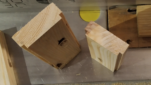
I cut some recesses on 2 corners of some 5 cm slats, cut them to length and mitered the ends. One recess would wrap around the edge of my PSU at the back of the extension and the other recess would house the metal front plate. I made a sufficiently large hole in one of the sides so some of the cable bundles with connector could pass thru. (I am not going to elaborate more on the wood working as it’s not the focus of this blog.)
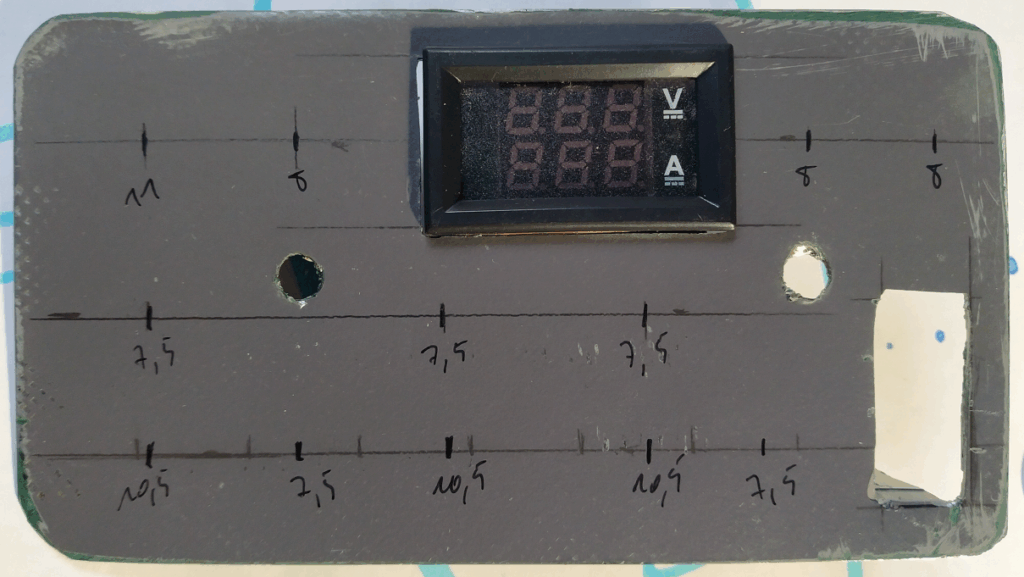
I cut a metal plate to size to fit just into the wood recesses. The openings for the meter and USB ports I cut out with a multitool. All the other holes I drilled.
For the USB ports, I only cut the opening on 3 sides. I bent the panel inside over the bottom edge. This way I created a little platform to which I could attach the USB ports.
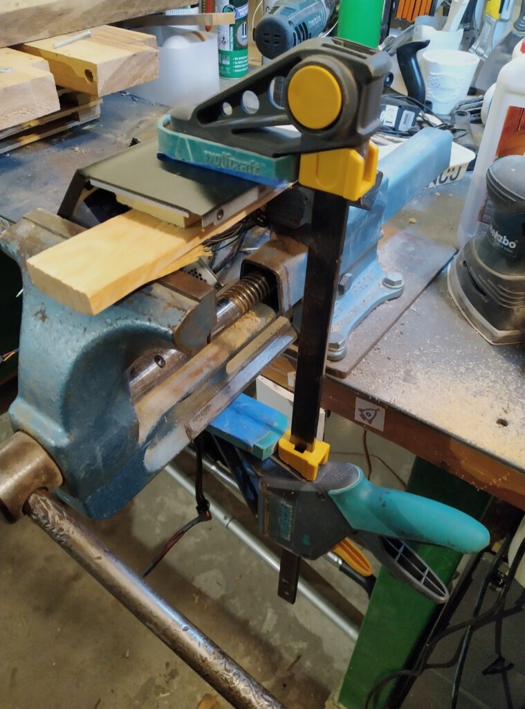
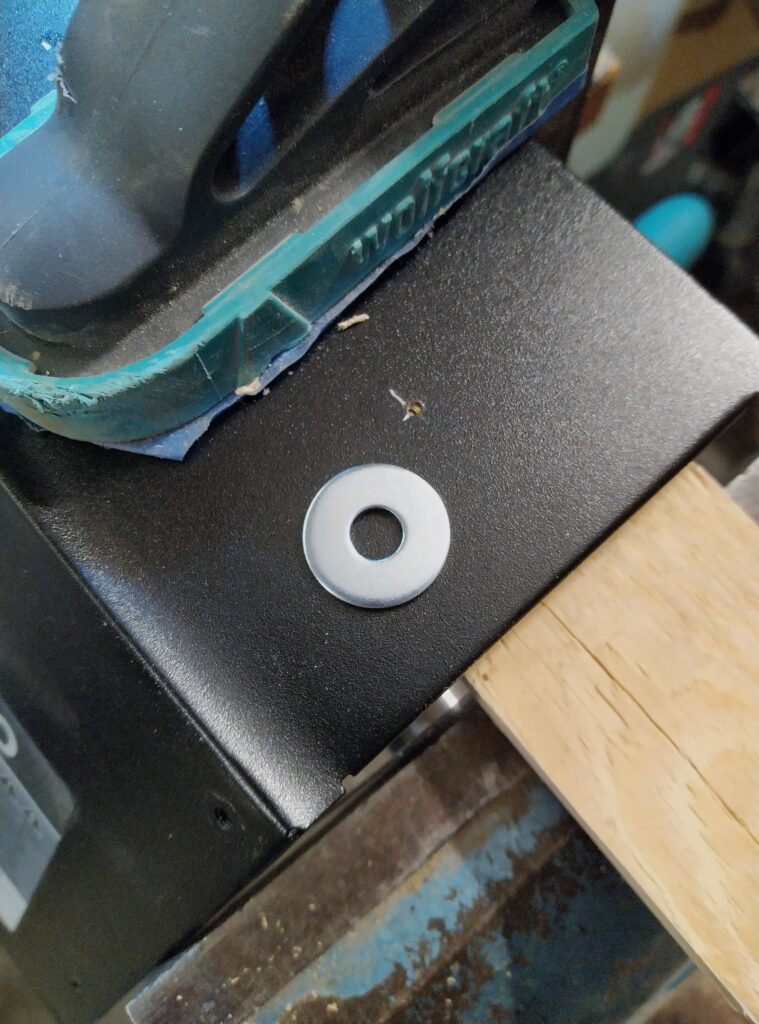
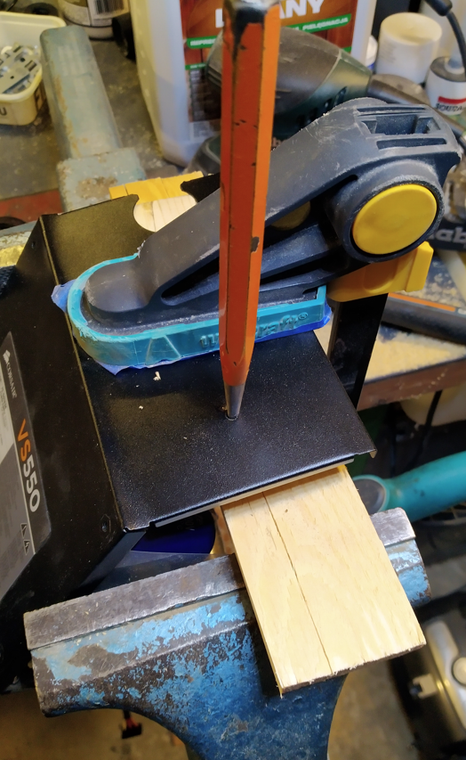
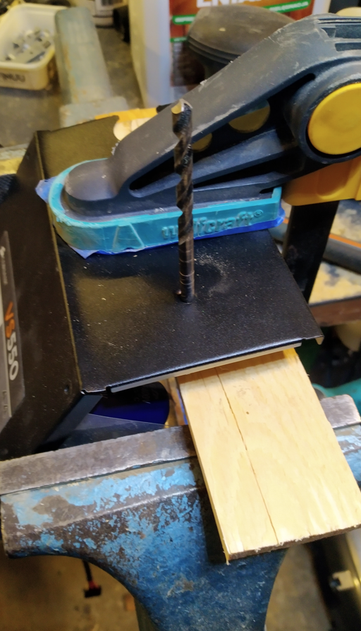
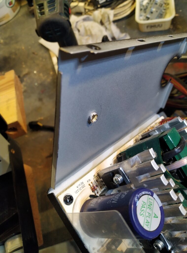
To screw the bolts for the extension into the PSU I wanted to see if I could thread the metal of the psu’s housing. For this I tried to create a 5mm bushing in/from the housing which could be threaded. I drilled a 1mm hole in the position where I wanted to attach the extension with a 6mm bolt. I bent open the housing of the PSU a little bit, just enough to be able to put some piece of soft wood underneath. I located a 6mm washer between the metal and the wood. I then started widening the hole by hammering a conical center punch through it. Whet it could fit a 5mm drill, I stopped. This way a small metal bushing is formed on the inside of the PSU. It’s not much but it was enough for me to put a 6mm thread in it so I can screw a bolt in it. I made 2 such holes. This solution will not hold tons but it is able to hold the extension tightly to the PSU (of course I didn’t overly tighten the bolts!).
Before starting the assembly I painted both the wooden frame and front panel white.
Flipping the ventilator
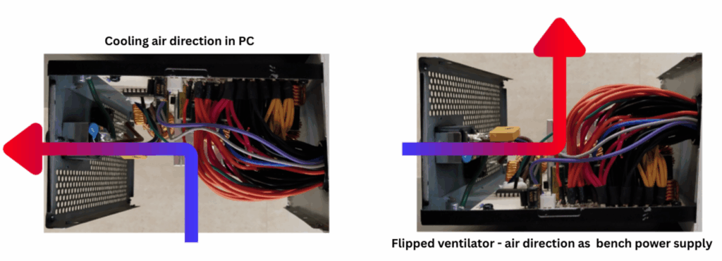
The psu was originally installed at the top op the pc. It was hanging upside down from the electronics point of view. The ventilator was pulling air from inside the pc case thru the psu out the back of the psu. Now as a bench power supply I am going to position it with the circuit board at the bottom and the electronics pointing upwards. The ventilator would now be pulling air from the top and blow out the back. This is not really the most efficient cooling. So I flipped the ventilator 180 degrees. It is now pulling air from the back and blowing out the hot air through the top.
Assembly
For the USB ports, I cut 2x double ports out of the old laptop’s print board. I left enough room behind the ports so I could use the print boards as a mounting support. I drilled holes through the print boards and a matching hole through the metal lip I left behind in the front panel. To avoid any short circuits I grinded away the tracks on the bottom and top of the circuit boards only leaving 2 positions to solder the +5V and ground wires. After soldering the wires and isolating them with some tape, I installed the ports with a long 3mm bolt and some nuts.
I gradually installed all the remaining components on the front panel and soldered the corresponding wires as I went along. Where considered necessary I applied shrinking tube.
Once everything was soldered I did a double check and folded all the wires inside while pushing the front panel in place. I then screwed in the long M6 bolts which I had previously cut to length. Honestly, I should have taken some wider wooden slats to make the extension. With all the wires and the components, it was a tight fit!
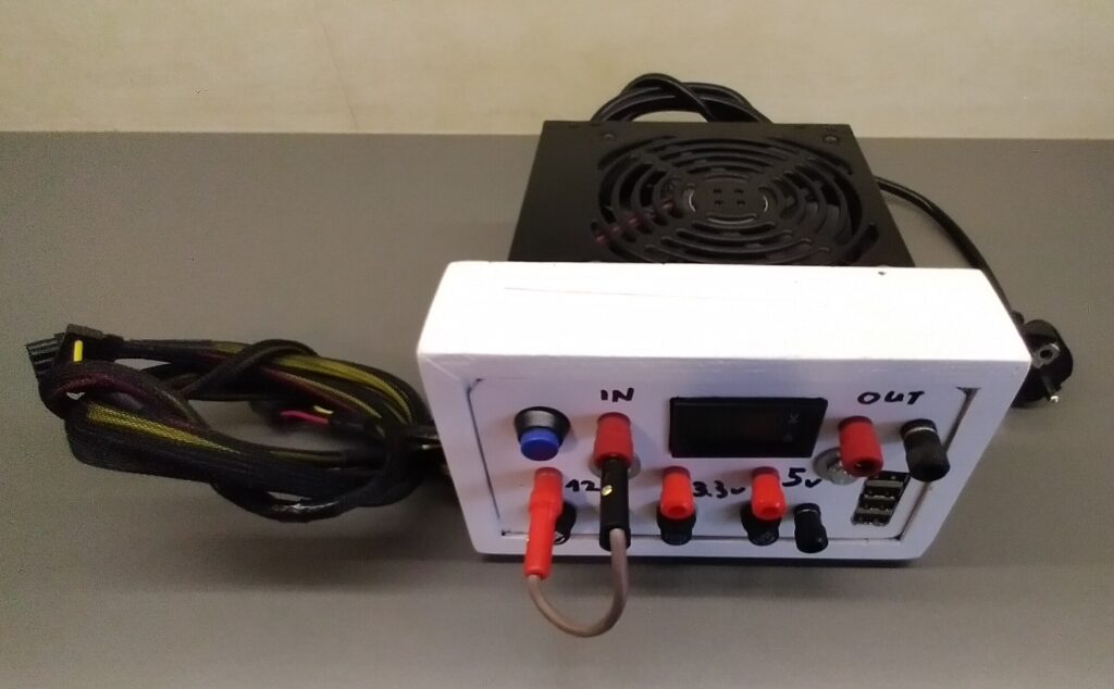
Once all assembled, I found a suitable load and let it run for an hour or so. All working great! Scroll down and you can see some pictures of the final result.
Stay tuned and find out what peripherals I will connect to the spare wire bundles!
[…] the stereo unit I will be using the PSU bench power supply which I described in a previous blog (https://eoncrafts.eu/convert-a-pc-psu-to-a-bench-power-supply/). I soldered a male 4-pin molex connector to the power leads of the car stereo so I will be able […]